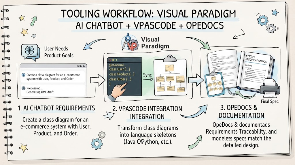
In the rapidly evolving landscape of software engineering, the gap between abstract ideas and concrete implementation is being bridged by intelligent tooling. One of the most powerful examples of this shift is the integration of Artificial Intelligence into the software design lifecycle using Visual Paradigm. This tutorial explores how modern architecture workflows can be streamlined by combining three critical components: AI Chatbots for requirements, VPasCode for instant synchronization, and OpeDocs for automated documentation.
The Modern Tooling Workflow
The contemporary software development process is no longer linear; it is a dynamic cycle of generation, transformation, and documentation. Visual Paradigm facilitates this through a three-phase workflow that transforms user intent into a fully documented system blueprint.
Phase 1: AI Chatbot Requirements
The journey begins with the most fundamental element of any project: the user need. Instead of manually drawing diagrams or writing verbose specifications, developers can now leverage AI assistants to translate abstract product goals into structured drafts.
- Natural Language Processing: Users input requirements in plain English. For example, a prompt like “Create a class diagram for an e-commerce system with User, Product, and Order” is sufficient to trigger the generation process.
- Instant UML Drafts: The AI interprets these prompts and immediately generates a Unified Modeling Language (UML) draft. This allows for rapid prototyping and immediate visualization of system logic.
Phase 2: VPasCode Integration
Once the visual model is established, the focus shifts to code generation and synchronization. This is where VPasCode (Visual Paradigm as Code) plays a pivotal role.
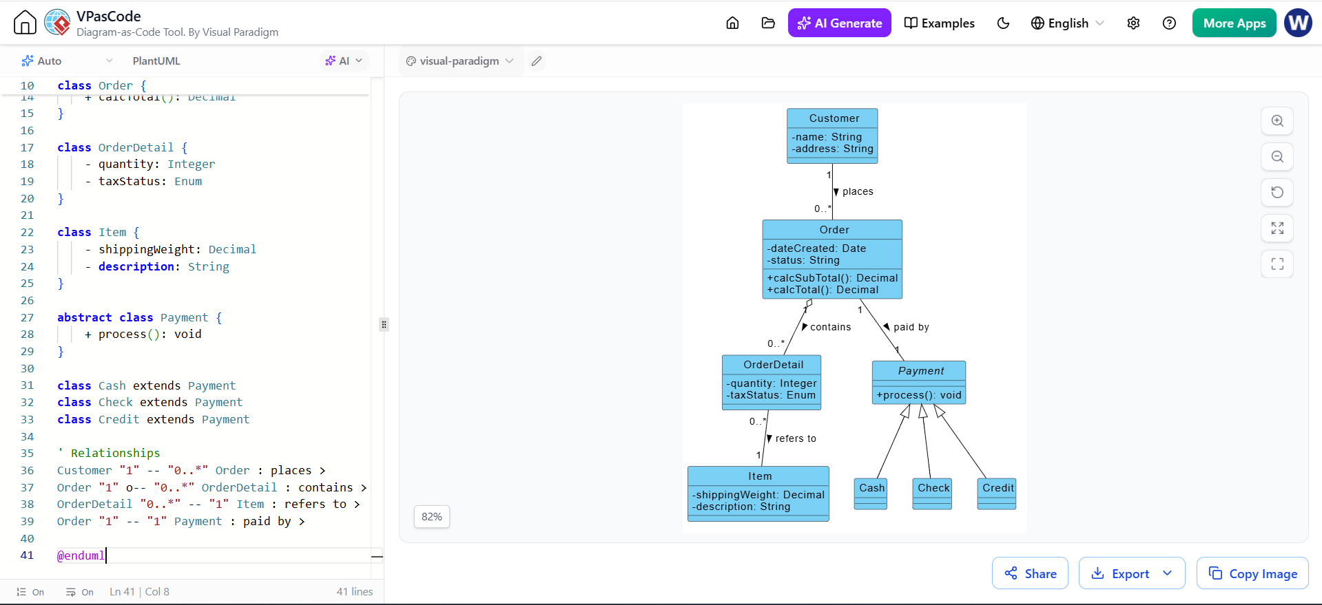
- Text-Based Syntax: VPasCode allows developers to work with text-based syntax (such as PlantUML) alongside visual models.
- Instant Synchronization: A key feature is the ability to instantly connect text-based skeletons to visual diagrams. If you edit the code, the diagram updates; if you move a box in the diagram, the code updates. This ensures that the visual representation and the codebase remain perfectly in sync.
- Language Support: The system can transform class diagrams into language skeletons for popular programming languages like Java, C#, and Python, ensuring the design is immediately actionable by developers.
Phase 3: OpeDocs & Documentation
The final phase of the workflow addresses the often-overlooked aspect of software engineering: documentation. OpeDocs automates the generation of specification documents.
- Traceability: It maintains a strict link between requirements and the final design, ensuring that every requirement has a corresponding implementation.
- Alignment: By automating the process, OpeDocs ensures that the design models are perfectly aligned with the final system specification documentation, eliminating the common issue of “stale” documentation.
Deep Dive: The Class Diagram
At the heart of the object-oriented design process lies the Class Diagram. In the context of the workflow above, this is the primary blueprint that connects the AI-generated requirements to the code skeletons.
A Class Diagram is a static structure diagram that describes the system’s classes, their attributes, operations (methods), and the relationships among objects. To understand the “System Blueprint” generated by Visual Paradigm, one must understand its core components.
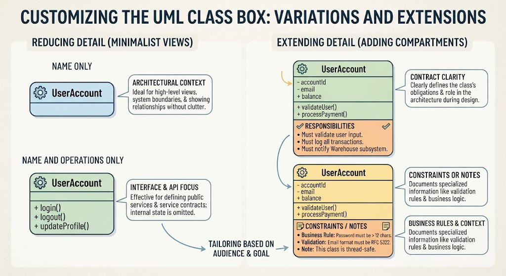
Core Components of a Class Diagram
1. Class Name
The class name appears at the top of the class box. It is typically bolded to distinguish it from other elements. For example, User, Product, or Order.
2. Attributes
Attributes are the variables that hold data within a class. They are listed in the middle section of the class box.
- Data Types: Examples include
sku(Stock Keeping Unit) orunitPrice. - Visibility: The access level of an attribute is denoted by specific symbols placed before the name:
+(Plus): Public (accessible from anywhere)-(Minus): Private (accessible only within the class)#(Hash): Protected (accessible within the class and its subclasses)
3. Operations
Operations represent the methods or behaviors the class can perform. These are listed in the bottom section of the class box.
- Examples: A method like
calculateSubtotal()defines a behavior. - Return Types: The data type returned by the method is specified after a colon (e.g.,
calculateSubtotal(): double).
4. Relationships
Relationships are the lines connecting different classes, indicating how they interact.
- Association: A general link between objects.
- Aggregation: A “has-a” relationship where parts can exist independently.
- Composition: A stronger “has-a” relationship where parts cannot exist without the whole.
- Inheritance: The “is-a” relationship where a class derives from another.
- Dependency: A usage relationship where one class relies on another.
Conclusion
By integrating AI capabilities, text-based syntax, and automated documentation, Visual Paradigm creates a robust environment for software design. Whether you are defining the attributes of an Order class or mapping the high-level requirements of an e-commerce system, this workflow ensures that your system blueprint is accurate, up-to-date, and ready for implementation.